
Core Summary
This engineering guide lays out a three-dimensional decision tree for CVD coating selection (atmosphere > temperature > CTE), clarifies SiC’s practical 1600°C limit and TaC’s vulnerability to oxidation, maps the causal chain from thermal-stress cracking to particle contamination, and provides a full-lifecycle management checklist from incoming inspection to replacement threshold. Built for epitaxy and PVT crystal-growth engineers who need to get the selection decision right, fast.
Author: Dr. Zhang, Senior Materials Engineer, Semicera
After more than a decade working with coating thermal fields, I’ve seen plenty of selection decisions go wrong — and it’s rarely because the material wasn’t good enough. It’s because whoever chose it never quite pinned down which operating regime they were actually in. In this guide, I’ll lay out the real boundaries, failure mechanisms, and full-lifecycle management standards for SiC and TaC coatings, in the hope that it saves you a few of the detours I’ve taken.
Chapter 1 — The Coating Selection Decision Tree
Key takeaway: The selection order is atmosphere purity > peak temperature > substrate thermal cycling — if the atmosphere doesn’t meet spec, TaC’s temperature advantage never gets a chance to matter.
The first question I usually get from engineers is: “Dr. Zhang, my furnace can run at 2000°C — shouldn’t I just go with TaC?” My answer is always the same question back: how pure is your atmosphere?
Selection can’t be decided by temperature limit alone. Three dimensions need to be checked together: which range the process peak temperature falls into, whether the atmosphere contains silicon vapor or trace oxygen, and how well the substrate type matches the coating’s thermal expansion. If any one of the three fails, a coating that “looks like it can handle more heat” can end up with a shorter actual service life.
My recommended order of evaluation: first confirm whether the atmosphere can be reliably held within an inert or reducing range — this is a harder constraint than temperature, because TaC will oxidize and spall continuously on contact with even trace oxygen, and its temperature advantage never materializes. Then check whether the peak temperature consistently exceeds the 1600°C threshold. Finally, factor in the substrate grade’s coefficient of thermal expansion (CTE) and the frequency of thermal cycling to judge whether interfacial stress stays within an acceptable range.
|
Judgment Dimension |
Criterion |
Conclusion |
|
Atmosphere purity |
Can it be reliably held in an inert/reducing atmosphere with no leak risk? |
If not achievable → rule out TaC outright, regardless of temperature |
|
Peak process temperature |
Does it consistently exceed 1600°C? |
Exceeds it and atmosphere meets spec → TaC; doesn’t exceed it → SiC offers better value |
|
Substrate & thermal cycling |
Substrate CTE match, heating/cooling frequency per furnace run |
High-frequency rapid cycling → favor the option with CTE closer to the substrate |
Chapter 2 — SiC Coating’s Performance Boundary: 1600°C Is a Watershed
Key takeaway: SiC coating’s boundary is set by a high-temperature volatilization reaction in H₂ atmosphere; its practical limit is around 1600°C, making it the best-value choice for processes at or below that temperature.
The performance boundary of SiC coating is governed by its decomposition reaction in hydrogen-containing atmospheres — not simple physical melting:
SiC(s) + 2H₂(g) → Si(g) + CH₄(g)
The equilibrium constant of this reaction rises exponentially with temperature, and the Si vapor partial pressure increases sharply in the 1550–1650°C range. That’s why engineering practice treats 1600°C as the practical upper limit for SiC coating — above that temperature, the coating doesn’t “melt,” its volatilization rate simply exceeds an acceptable rate of lifespan loss. The higher the H₂ partial pressure and the lower the total pressure, the earlier this inflection point shifts — meaning two coatings both nominally rated “1600°C” can show several-fold differences in actual lifespan depending on furnace type and gas mixture.
In terms of corrosion resistance, SiC coating shows good chemical inertness against common MOCVD atmospheres such as HCl, H₂, and NH₃, which is why it’s widely used in mid-to-low-temperature processes such as GaN MOCVD, UV LED, gallium oxide epitaxy, and Si epitaxy. In GaN MOCVD processes around 1100°C, an optimized SiC coating can withstand more than 150 thermal-shock cycles at ΔT = 1100°C without noticeable cracking.
Here’s a case from last year. We helped a UV LED customer optimize the SiC-coated graphite trays in their MOCVD process. Their process ran at 1100°C, using imported trays that were stuck at around 120 cycles of lifespan, with cracks always appearing at the edges first. We ran a cross-sectional SEM analysis and found the coating thickness differed by nearly 30% between the center and the edge — the edge deposition was too thin.
We then adjusted the deposition fixture, tightening thickness uniformity from ±15% to within ±5%, and increased the thickness from 100μm to 130μm. Under the same process conditions, tray lifespan went from 120 to 180 cycles, and particle counts per furnace run dropped 40%. The customer worked out the numbers: roughly ¥120,000 saved per MOCVD tool per year in tray procurement costs — over ¥700,000 a year across their six tools.
Typical applications cluster in production lines where the process peak temperature stays at or below 1600°C and coating cost sensitivity is high — in this range, SiC coating offers better value than TaC and is the default choice for most MOCVD epitaxy furnaces.
Chapter 3 — TaC Coating’s Performance Boundary: High Temperature Tolerance, But Oxygen-Sensitive
Key takeaway: TaC coating has a higher temperature ceiling, but oxidation is more dangerous than heat itself — in a trace-oxygen environment, its actual lifespan can fall below that of SiC.
TaC coating’s core advantages lie in two areas: an extremely high temperature ceiling, and a radiative emissivity far lower than SiC’s. But realizing that temperature advantage comes with a precondition that’s often overlooked — atmosphere purity.
TaC has a melting point of 3880°C and can maintain a near-stoichiometric, stable structure above 2000°C — far exceeding SiC’s practical temperature limit. But the moment even a trace oxygen partial pressure is present in the system, TaC oxidizes according to:
2TaC(s) + 7/2 O₂(g) → Ta₂O₅(s) + 2CO₂(g)
The Pilling–Bedworth ratio of Ta₂O₅ to TaC exceeds 2, so the volume expansion of the oxidation product generates additional internal stress in the coating. The oxide layer itself offers no protection either — it continuously spalls off, exposing fresh surface and driving accelerated oxidation. In other words, TaC coating is stable to a “near-zero thermal loss” level in vacuum or pure argon/hydrogen environments, but if the furnace has any leaks or the process gas contains trace oxygen, TaC’s actual lifespan can end up lower than SiC’s. Choosing TaC isn’t a universal win just because it “handles higher temperatures” — it only pays off if atmosphere purity can actually be guaranteed.
Choosing TaC isn’t a universal win just because it “handles higher temperatures” — it only pays off if atmosphere purity can actually be guaranteed.
Low emissivity is another engineering advantage of TaC: at 1000°C, TaC coating has a normal emissivity of about 0.3–0.43, significantly lower than SiC coating’s 0.85–0.9 range. This means TaC-coated components maintain more uniform surface temperatures at the same heating power, and also help reduce overall power consumption.
Typical applications cluster in high-purity crystal-growth furnace thermal fields for SiC PVT crystal growth and ultra-high-temperature epitaxy, where peak temperature exceeds 1600°C and the atmosphere can be controlled to inert/reducing conditions.
Chapter 4 — The Four Failure Mechanisms of Coatings
Key takeaway: The four failure mechanisms aren’t isolated — CTE mismatch is the root cause of thermal-stress cracking, and cracking is in turn a primary source of particle contamination. Troubleshooting should follow this causal chain.
Coating failure is rarely caused by a single factor. It’s usually the interplay of four mechanisms — thermal-stress cracking, CTE mismatch, chemical corrosion, and particle contamination — and there’s a causal chain running through them: CTE mismatch is the root cause of thermal-stress cracking, and cracking is one of the primary sources of particle contamination.
4.1 Thermal-Stress Cracking
The coating is bonded to a graphite substrate, and the two can never have perfectly matched thermal expansion coefficients. The high deposition temperature of the CVD process itself generates residual thermal stress during cooling. During heating/cooling cycles, stress accumulates at the interface in proportion to the temperature differential:
σ ≈ E·Δα·ΔT / (1 − ν)
Where E is the coating’s elastic modulus, Δα is the CTE difference between coating and substrate, ΔT is the temperature change, and ν is Poisson’s ratio. This equation tells us two things:
1. Halving Δα roughly halves the interfacial stress — so choosing the substrate grade (especially the orientation of anisotropic graphite) is itself a lifespan-extension lever, not purely a coating-material issue.
2. Stress is proportional to ΔT, and rapid cooling induces cracking more readily than dwelling at high temperature — many field cases attribute cracking to “temperature being too high,” when the real root cause on inspection is usually a cooling rate set too fast.
Crack nucleation sites follow a pattern too. CVD-grown SiC coating forms a columnar-grain structure, and grain boundaries are inherent stress-concentration points; combined with the faceted coating surface, sharp corners with small local radii of curvature become preferred sites for microcrack nucleation. Once a crack forms, it tends to propagate preferentially along columnar grain boundaries rather than transgranularly — which is why cracks often appear “dendritic” rather than straight-line under optical inspection.
4.2 CTE Mismatch
It’s worth noting that SiC’s coefficient of thermal expansion (about 4.0–4.5×10⁻⁶/K) is actually closer to that of most graphite substrates than TaC’s (about 6.3–6.6×10⁻⁶/K). TaC typically has a larger CTE mismatch with graphite substrates, which can result in even higher interfacial stress under frequent thermal-cycling conditions.
This is why the intuitive assumption that “higher temperature tolerance = safer” often backfires on production lines with frequent furnace start-stop cycles. TaC coating’s Ta/C composition ratio also needs to be controlled — deviation from stoichiometry further widens the thermal-expansion gap and worsens interfacial mismatch risk.
4.3 Chemical Corrosion
The mechanisms of chemical corrosion were covered in Chapters 2 and 3: SiC coating’s boundary is set by a high-temperature volatilization reaction in hydrogen-containing atmospheres; TaC coating’s boundary is set by oxidation-driven spalling caused by trace oxygen.
What the two have in common: corrosion rate doesn’t change linearly — there’s a critical inflection point tied to temperature or atmosphere concentration, and the closer you operate to that point, the greater the batch-to-batch variation in lifespan.
4.4 Particle Contamination
Particle-contamination sources fall into four categories: coating wear, debris shedding from microcrack propagation, secondary dust stirred up by gas-flow turbulence, and external contamination introduced during maintenance. The trend curve of particle count is more informative than any single reading — small fluctuations during a stable period are normal wear, but once the curve enters a sustained upward slope, it usually means microcracks have already propagated through the full coating thickness. That’s the early-warning signal for a replacement window — don’t wait until the count exceeds the spec limit to respond.
Engineering note: Last year a SiC epitaxy customer reported that a batch of SiC-coated trays showed a clear rise in particle count at the edge region after roughly 200 hours of use. Investigation found that this region sat close to the gas inlet, where temperature fluctuation reached ±15°C — well above the ±3°C seen at the chamber center. The root cause wasn’t the coating batch itself, but a gas-flow distribution issue that drove up both the frequency and amplitude of local temperature cycling. The fix: rebalance the heating-zone power in that region and increase coating thickness there from a standard 100μm to 150μm. The takeaway: root-cause analysis for particle issues can’t stop at the coating itself — the thermal field and gas-flow distribution need to be examined together.
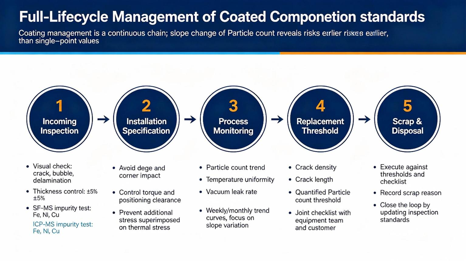
Chapter 5 — Full Lifecycle Management of Coated Components
Key takeaway: Coating management is a continuous chain from incoming inspection to disposal — the slope of the particle-count trend reveals problems earlier than any single-point reading.
From incoming inspection to disposal, there are four stages in a coated component’s life that deserve dedicated inspection steps or standard procedures — rather than waiting until an obvious defect shows up.
5.1 Incoming Inspection
- ● Visual inspection: cracks, bubbles, localized delamination
- ● Thickness uniformity: recommend controlling to within ±5% of the nominal value, spot-checked via eddy-current thickness gauging or cross-sectional SEM
- ● Purity report: verify total metallic impurity content (via ICP-MS or GDMS), with particular attention to residual transition metals such as Fe, Ni, and Cu that are sensitive for semiconductor processes
Semicera’s delivery standard: every batch of coated components ships with a full-element GDMS analysis report, with total impurity content controlled below 5 ppm and key transition-metal elements below 0.1 ppm.
5.2 Installation Specification
Installation specification: coated components should be handled carefully during assembly and transport to avoid impacts on edges and corners — coating edges and corners are inherent stress-concentration zones, and mechanical damage there directly becomes a preferred crack-propagation starting point during thermal cycling. Fastening torque and positioning clearance should follow design tolerances to avoid adding extra stress on top of the thermal stress already generated during heating/cooling.
5.3 Process Monitoring
Process monitoring: the core indicators are particle-count trend, temperature uniformity, and changes in vacuum/leak rate. We recommend building weekly or monthly trend curves rather than looking only at single-point values — the change in slope reveals problems earlier than the absolute value does.
5.4 Replacement Threshold
Replacement threshold: the specific scrap thresholds for crack density, individual crack length, and particle count vary depending on product design and customer process tolerance. We recommend jointly defining a quantified checklist with your equipment team as part of the acceptance standard, rather than relying on visual judgment alone.
Semicera provides full-lifecycle data hosting service: each batch of coated components comes with a unique traceability code, with data accessible across the full chain — from incoming inspection, installation records, and process monitoring to end-of-life assessment. Our technical team proactively follows up at key milestones to help customers build a health record for their coated components.
Frequently Asked Questions
Q1: My process temperature is around 1550°C — should I choose SiC or TaC?
1550°C sits right at the critical edge of SiC’s practical temperature limit. If the atmosphere is well-controlled (inert/reducing, no leaks) and thermal cycling isn’t frequent (≤2 furnace start-stops per day), SiC coating can handle it. But if the furnace has even a slight leak or cycles frequently, we’d recommend TaC. My advice: first check your furnace’s actual leak-rate data and cooling curve, then decide.
Q2: Does TaC coating really never fail in vacuum?
In vacuum or pure argon/hydrogen environments, TaC’s stability is genuinely excellent — it stays structurally stable above 2000°C. But “vacuum” isn’t a single quality level — if the vacuum isn’t deep enough, or there’s a micro-leak, trace oxygen will trigger the oxidation reaction. In real cases, many premature TaC failures aren’t caused by temperature — they’re caused by atmosphere purity falling short of spec.
Q3: There are microcracks on the coating surface — can it still be used?
It depends on crack depth and density. Shallow surface microcracks (depth <20% of coating thickness) are a normal occurrence during thermal cycling, and the component can keep running while you closely monitor the particle-count trend. Once cracks propagate through the full coating thickness, or the particle count enters a sustained upward slope, it’s time to replace it. We recommend a weekly surface inspection with logged records — the trend is more informative than any single reading.
Q4: How much does lifespan drop after a coated component is reworked and recoated?
It depends on the substrate condition and the recoating process. Generally, if the substrate shows no significant corrosion or deformation, a recoated component can reach 80%–90% of the original coating’s lifespan. But if the substrate already has CTE-mismatch-induced deformation or interfacial damage, the recoating results will fall well short. Our general recommendation to customers: after 2–3 recoating cycles on the original component, it’s time for a new substrate — the economics no longer work out beyond that point.
Final Thoughts
After all these years working with coating thermal fields, my biggest takeaway is this: there’s no universal formula for coating selection — only “knowing your operating conditions well enough, and being honest enough about the material’s boundaries.”
SiC has its strengths — strong cost-effectiveness, a mature process, more than sufficient below 1600°C. TaC has its own strengths — handles ultra-high temperatures, low emissivity, near-zero loss in vacuum. But both have clearly defined boundaries, and cross them, and neither material holds up.
What Semicera offers goes beyond selling coated components. Our technical team can help with three things: first, a free assessment of your current operating conditions to determine whether SiC or TaC better suits your furnace; second, full delivery from surveying and machining through coating and quality control, with a GDMS purity report included with every batch; third, building a health record for your coated components, with regular follow-ups, trend analysis, and replacement alerts — so you don’t have to keep track of when it’s time to replace them yourself.
References
[1] Zhao Ximeng, Sun Benzhe, Qi Yang. Microscopic Mechanism Analysis of Fracture Modes and Failure in CVD Multilayer Coatings [J]. Cemented Carbide, 2023, 40(1): 42.
[2] Jeong J H, Lee S Y, Kwon D I, et al. Mechanical Analysis for Thermal Cracking Control in CVD-Processed Diamond Thick Films for Electronic Applications [J]. Korean Journal of Metals and Materials.
[3] Japanese Patent JP4641533B2. Carbon Composite Material for Reducing-Atmosphere Furnaces and Its Manufacturing Method.
[4] US Patent US20100190353A1. Nanolayer Deposition Process.
Further Reading
The cluster pages below expand more fully on the mechanisms and data covered in this article:
|
Cluster Page |
Corresponding Chapter |
Title |
|
Cluster Page 1 |
Chapter 1 |
SiC vs TaC 3D Selection Decision Matrix: Quantified Criteria for Temperature, Atmosphere, and CTE |
|
Cluster Page 2 |
Chapter 2 |
SiC Coating’s Corrosion Resistance Data and Lifespan Optimization Practice in MOCVD Epitaxy |
|
Cluster Page 3 |
Chapter 3 |
TaC Coating’s Chemical Stability Boundary in Ultra-High-Temperature SiC PVT Crystal Growth |
|
Cluster Page 4 |
Chapter 4 |
Mechanical Modeling of Thermal-Stress Cracking and the Temperature Bifurcation Point: Why Do Cracks Always Start at the Edge? |
|
Cluster Page 5 |
Chapter 5 |
Full Lifecycle Management of Coated Components: Incoming Inspection, Process Monitoring, and Replacement Threshold Guide |
Post time: Sep-03-2026